Which of the Following Can Route Layer 3
Example: Interconnecting a Layer two VPN with a Layer iii VPN
This instance provides a stride-by-pace procedure and commands for interconnecting and verifying a Layer 2 VPN with a Layer 3 VPN. It contains the following sections:
Requirements
This example uses the following hardware and software components:
-
Junos OS Release ix.3 or later
-
Five MX Series routers
-
3 Thousand Serial routers
-
Two T Series routers
This configuration example has been tested using the software release listed and is causeless to work on all later releases.
Overview and Topology
A Layer 2 VPN is a type of virtual private network (VPN) that uses MPLS labels to transport information. The communication occurs between the provider edge (PE) routers.
Layer 2 VPNs utilise BGP as the signaling protocol and, consequently, have a simpler design and require less provisioning overhead than traditional VPNs over Layer two circuits. BGP signaling too enables autodiscovery of Layer 2 VPN peers. Layer two VPNs can take either a total-mesh or a hub-and-spoke topology. The tunneling mechanism in the core network is, typically, MPLS. However, Layer ii VPNs can as well use other tunneling protocols, such as GRE.
Layer 3 VPNs are based on RFC 2547bis, BGP/MPLS IP VPNs. RFC 2547bis defines a machinery by which service providers tin use their IP backbones to provide VPN services to their customers. A Layer 3 VPN is a set of sites that share common routing information and whose connectivity is controlled by a collection of policies. The sites that make up a Layer three VPN are connected over a provider'southward existing public Internet backbone. RFC 2547bis VPNs are besides known every bit BGP/MPLS VPNs because BGP is used to distribute VPN routing information beyond the provider's courage, and MPLS is used to forward VPN traffic beyond the courage to remote VPN sites.
Client networks, because they are private, tin can utilise either public addresses or individual addresses, every bit defined in RFC 1918, Accost Resource allotment for Private Internets. When customer networks that utilize private addresses connect to the public Internet infrastructure, the individual addresses might overlap with the same private addresses used by other network users. MPLS/BGP VPNs solve this problem past adding a route distinguisher. A road distinguisher is a VPN identifier prefix that is added to each address from a detail VPN site, thereby creating an address that is unique both inside the VPN and within the Net.
In addition, each VPN has its own VPN-specific routing table that contains the routing data for that VPN only. To separate a VPN'southward routes from routes in the public Internet or those in other VPNs, the PE router creates a dissever routing table for each VPN called a VPN routing and forwarding (VRF) table. The PE router creates one VRF table for each VPN that has a connection to a customer edge (CE) router. Whatsoever customer or site that belongs to the VPN tin access only the routes in the VRF tables for that VPN. Every VRF table has one or more extended customs attributes associated with it that identify the route as belonging to a specific collection of routers. One of these, the route target attribute, identifies a collection of sites (VRF tables) to which a PE router distributes routes. The PE router uses the route target to constrain the import of remote routes into its VRF tables.
When an ingress PE router receives routes advertised from a directly continued CE router, it checks the received route confronting the VRF consign policy for that VPN.
-
If information technology matches, the route is converted to VPN-IPv4 format—that is, the route distinguisher is added to the route. The PE router then announces the route in VPN-IPv4 format to the remote PE routers. Information technology besides attaches a route target to each route learned from the directly connected sites. The route target attached to the route is based on the value of the VRF table's configured export target policy. The routes are and so distributed using IBGP sessions, which are configured in the provider's core network.
-
If the road from the CE router does non friction match, it is non exported to other PE routers, but information technology tin can still be used locally for routing, for case, if two CE routers in the same VPN are directly continued to the same PE router.
When an egress PE router receives a route, information technology checks it against the import policy on the IBGP session betwixt the PE routers. If it is accepted, the router places the road into its bgp.l3vpn.0 table. At the same time, the router checks the route confronting the VRF import policy for the VPN. If it matches, the route distinguisher is removed from the road and the route is placed into the VRF table (the routing-instance-proper name.inet.0 table) in IPv4 format.
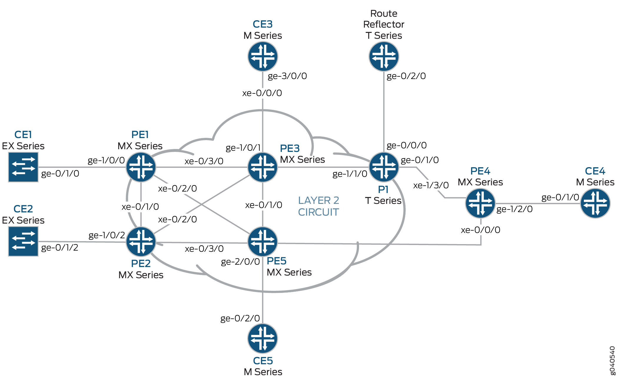
Effigy i shows the physical topology of a Layer 2 VPN-to-Layer 3 VPN interconnection.
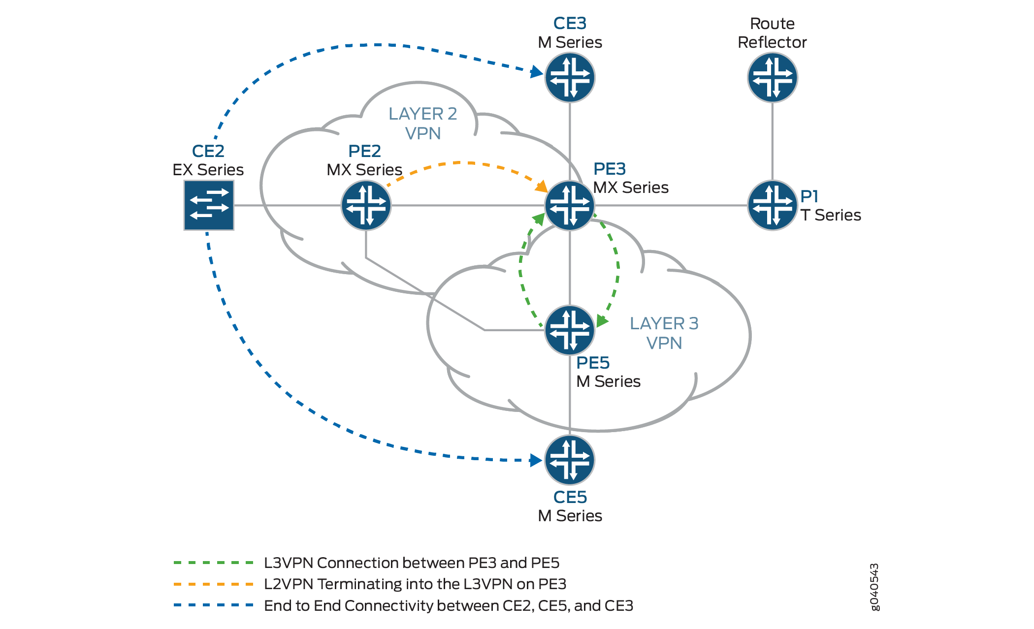
The logical topology of a Layer 2 VPN-to-Layer 3 VPN interconnection is shown in Effigy 2.
The following definitions describe the pregnant of the device abbreviations used in Figure 1 and Figure 2.
-
Customer border (CE) device—A device at the client premises that provides access to the service provider'due south VPN over a data link to 1 or more provider edge (PE) routers.
Typically the CE device is an IP router that establishes an adjacency with its directly connected PE routers. Subsequently the adjacency is established, the CE router advertises the site'due south local VPN routes to the PE router and learns remote VPN routes from the PE router.
-
Provider edge (PE) device—A device, or set of devices, at the border of the provider network that presents the provider's view of the customer site.
PE routers substitution routing data with CE routers. PE routers are aware of the VPNs that connect through them, and PE routers maintain VPN state. A PE router is only required to maintain VPN routes for those VPNs to which information technology is directly attached. After learning local VPN routes from CE routers, a PE router exchanges VPN routing data with other PE routers using IBGP. Finally, when using MPLS to forward VPN data traffic across the provider's backbone, the ingress PE router functions every bit the ingress label-switching router (LSR) and the egress PE router functions as the egress LSR.
-
Provider (P) device—A device that operates inside the provider's cadre network and does not directly interface to any CE.
Although the P device is a key part of implementing VPNs for the service provider's customers and may provide routing for many provider-operated tunnels that vest to dissimilar VPNs, it is not itself VPN-aware and does not maintain VPN state. Its principal office is allowing the service provider to calibration its VPN offerings, for example, by acting as an aggregation point for multiple PE routers.
P routers function as MPLS transit LSRs when forwarding VPN data traffic betwixt PE routers. P routers are required only to maintain routes to the provider's PE routers; they are not required to maintain specific VPN routing information for each customer site.
Configuration
To interconnect a Layer 2 VPN with a Layer three VPN, perform these tasks:
-
Configuring the Base Protocols and Interfaces
-
Configuring the VPN Interfaces
Configuring the Base Protocols and Interfaces
Step-by-Step Procedure
- On each PE and P router, configure OSPF with traffic engineering extensions on all interfaces. Disable OSPF on the fxp0.0 interface.
- On all the core routers, enable MPLS on all interfaces. Disable MPLS on the fxp0.0 interface.
- On all the core routers, create an internal BGP peer group and specify the route reflector address (7.7.seven.seven) as the neighbor. Likewise enable BGP to carry Layer 2 VPLS network layer reachability information (NLRI) messages for this peer group by including the signaling statement at the [edit protocols bgp grouping group-name family l2vpn] hierarchy level.
- On Router PE3, create an internal BGP peer group and specify the route reflector IP accost (7.7.seven.7) as the neighbor. Enable BGP to carry Layer ii VPLS NLRI messages for this peer group and enable the processing of VPN-IPv4 addresses by including the unicast statement at the [edit protocols bgp group group-name family inet-vpn] hierarchy level.
- For the Layer 3 VPN domain on Router PE3 and Router PE5, enable RSVP on all interfaces. Disable RSVP on the fxp0.0 interface.
- On Router PE3 and Router PE5, create label-switched paths (LSPs) to the route reflector and the other PE routers. The following case shows the configuration on Router PE5.
- On Routers PE1, PE2, PE3, and PE5, configure the core interfaces with an IPv4 accost and enable the MPLS address family. The following example shows the configuration of the xe-0/1/0 interface on Router PE2.
- On Router PE2 and Router PE3, configure LDP for the Layer two VPN MPLS signaling protocol for all interfaces. Disable LDP on the fxp0.0 interface. (RSVP tin can besides be used.)
- On the route reflector, create an internal BGP peer grouping and specify the PE routers IP addresses as the neighbors.
- On the route reflector, configure MPLS LSPs towards Routers PE3 and PE5 to resolve the BGP next hops from inet.iii routing table.
Configuring the VPN Interfaces
Footstep-by-Step Process
Router PE2 is one end of the Layer 2 VPN. Router PE3 is performing the Layer two VPN stitching between the Layer 2 VPN and the Layer 3 VPN. Router PE3 uses the logical tunnel interface (lt interface) configured with different logical interface units applied under 2 unlike Layer 2 VPN instances. The bundle is looped though the lt interface configured on Router PE3. The configuration of Router PE5 contains the PE-CE interface.
- On Router PE2, configure the ge-1/0/2 interface encapsulation. Include the encapsulation statement and specify the ethernet-ccc option (vlan-ccc encapsulation is besides supported) at the [edit interfaces ge-1/0/2] bureaucracy level. The encapsulation should be the aforementioned in a whole Layer 2 VPN domain (Routers PE2 and PE3). Also, configure interface lo0.
- On Router PE2, configure the routing instance at the [edit routing-instances] hierarchy level. As well, configure the Layer 2 VPN protocol at the [edit routing-instances routing-instances-name protocols] hierarchy level. Configure the remote site ID every bit 3. Site ID three represents Router PE3 (Hub-PE). The Layer 2 VPN is using LDP as the signaling protocol. Be aware that in the post-obit example, both the routing instance and the protocol are named l2vpn.
- On Router PE5, configure the Gigabit Ethernet interface for the PE-CE link ge-2/0/0 and configure the lo0 interface.
- On Router PE5, configure the Layer iii VPN routing example (L3VPN) at the [edit routing-instances] bureaucracy level. As well configure BGP at the [edit routing-instances L3VPN protocols] hierarchy level.
- In an MX Serial router, such every bit Router PE3, you must create the tunnel services interface to be used for tunnel services. To create the tunnel service interface, include the bandwidth statement and specify the amount of bandwidth to reserve for tunnel services in gigabits per second at the [edit chassis fpc slot-number flick slot-number tunnel-services] hierarchy level.
- On Router PE3, configure the Gigabit Ethernet interface.
Include the address argument at the [edit interfaces ge-1/0/i.0 family unit inet] hierarchy level and specify 90.90.90.one/24 every bit the IP accost.
- On Router PE3, configure the lt-1/ane/10.0 logical tunnel interface at the [edit interfaces lt-1/i/10 unit of measurement 0] bureaucracy level. Router PE3 is the router that is stitching the Layer 2 VPN to the Layer three VPN using the logical tunnel interface. The configuration of the peer unit of measurement interfaces is what makes the interconnection.
To configure the interface, include the encapsulation statement and specify the ethernet-ccc option. Include the peer-unit statement and specify the logical interface unit one as the peer tunnel interface. Include the family statement and specify the ccc choice.
- On Router PE3, configure the lt-1/1/10.i logical tunnel interface at the [edit interfaces lt-ane/i/10 unit of measurement 1] hierarchy level.
To configure the interface, include the encapsulation statement and specify the ethernet option. Include the peer-unit statement and specify the logical interface unit 0 as the peer tunnel interface. Include the family argument and specify the inet selection. Include the address statement at the [edit interfaces lt-1/1/10 unit 0] hierarchy level and specify 70.70.seventy.i/24 as the IPv4 address.
-
On Router PE3, add the lt interface unit i to the routing instance at the [edit routing-instances L3VPN] hierarchy level. Configure the instance type as vrf with lt peer-unit i as a PE-CE interface to stop the Layer 2 VPN on Router PE2 into the Layer three VPN on Router PE3.
- On Router PE3, add the lt interface unit 0 to the routing case at the [edit routing-instances protocols l2vpn] hierarchy level. Also configure the same vrf target for the Layer 2 VPN and Layer 3 VPN routing instances, so that the routes can be leaked between the instances. The example configuration in the previous step shows the vrf target for the L3VPN routing instance. The following example shows the vrf target for the l2vpn routing case.
- On Router PE3, configure the policy-statement statement to export the routes learned from the directly connected lt interface unit 1 to all the CE routers for connectivity, if needed.
Results
The post-obit output shows the full configuration of Router PE2:
Router PE2
The post-obit output shows the last configuration of Router PE5:
Router PE5
The following output shows the final configuration of Router PE3:
Router PE3
Verification
Verify the Layer ii VPN-to-Layer 3 VPN interconnection:
-
Verifying Router PE2 VPN Interface
-
Verifying Router PE3 VPN Interface
-
Verifying Terminate-to-End connectivity from Router CE2 to Router CE5 and Router CE3
Verifying Router PE2 VPN Interface
Purpose
Bank check that the Layer 2 VPN is up and working at the Router PE2 interface and that all the routes are there.
Activeness
-
Apply the testify l2vpn connections command to verify that the connection site ID is 3 for Router PE3 and that the status is Up.
user@PE2> show l2vpn connections -
Utilise the show route tabular array control to verify that the Layer two VPN road is present and that there is a next hop of 10.10.five.ii through the xe-0/two/0.0 interface. The post-obit output verifies that the Layer 2 VPN routes are nowadays in the l2vpn.l2vpn.0 table. Similar output should be displayed for Router PE3.
user@PE2> testify route table l2vpn.l2vpn.0 -
Verify that Router PE2 has a Layer 2 VPN MPLS label pointing to the LDP label to Router PE3 in both directions (Push button and Pop).
user@PE2> show route table mpls.0
Meaning
The l2vpn routing instance is up at interface ge-one/0/two and the Layer two VPN route is shown in tabular array l2vpn.l2vpn.0. Table mpls.0 shows the Layer 2 VPN routes used to forward the traffic using an LDP label.
Verifying Router PE3 VPN Interface
Purpose
Bank check that the Layer 2 VPN connection from Router PE2 and Router PE3 is Up and working.
Action
-
Verify that the BGP session with the route reflector for the family l2vpn-signaling and the family inet-vpn is established.
user@PE3> bear witness bgp summary -
The following output shows the L3VPN.inet.0 routing table, which has Routers CE1, CE3, and CE5 listed.
user@PE3> show route table L3VPN.inet.0 -
The post-obit output verifies the Layer 2 VPN route and the characterization associated with it.
user@PE3> testify route table l2vpn.l2vpn.0 detail -
The following output show the L2VPN MPLS.0 route in the mpls.0 route table.
user@PE3> show route tabular array mpls.0 -
Use the show road tabular array mpls.0 command with the detail option to meet the BGP attributes of the route such as next-hop type and label operations.
user@PE5> show route table mpls.0 particular
Verifying End-to-Cease connectivity from Router CE2 to Router CE5 and Router CE3
Purpose
Check the connectivity between Routers CE2, CE3, and CE5.
Activity
- Ping the Router CE3 IP address from Router CE2.
user@CE2> ping ninety.90.90.two # CE3 IP accost - Ping the Router CE5 IP address from Router CE2.
user@CE2> ping 80.80.eighty.two # CE5 IP address
Source: https://www.juniper.net/documentation/en_US/release-independent/nce/topics/example/layer-2-vpn-layer-3-vpn-connection-configuring.html
0 Response to "Which of the Following Can Route Layer 3"
Post a Comment